How is an mrt equipment made?
(Reading time: 3 min)
Magneto inductive equipment is made for inspecting the inner and the outer part of ferro-magnetic ropes. The measuring head and the acquisition system constitutes the MRT equipment.
In this article, you will learn the basic structure of this inspecting tool.
MEASURING HEAD
The measuring head or detector is made of magnets and sensors. Magnets induce a magnetic flux inside the rope to fully saturate it. Neodymium-Iron-Boron alloy (NdFeB) is a magnets combination providing a magnetic field more intense than others. This characteristic allows the magnetic flux to penetrate deeper inside the rope. If there are no defects inside the ropes, the magnetic flux flows without interruption. (Picture 1.)

(Picture 1. Absence of defects)
When broken wires or defects occur, a modification of the magnetic flux lines appears (Picture 2.). This change, in value and direction, is detected by sensors that transform the physical phenomena in a readable signal. The closer the sensors are to the rope, the better is the result in terms of sensitivity.

Depending on the inspection environment the shape of the device varies. The standard configuration for mobile application is a close architecture (Picture 3.), whilst in the cableway sector it is preferable an open architecture for hauling ropes (Picture 4.) because the device must pass on cableway slings (video).

(Picture 3. Mobile Device – Close Architecture)
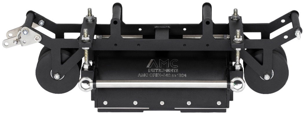
(Picture 4. Mobile Device – Open Architecture)
Both configurations allow the technician to inspect specific diameter range. To detect lower diameter range it is preferable to use a reduction bushing kit (we have already seen in the previous page that the closer the sensors are to the rope the better is the signal)
2. THE ACQUISITION SYSTEM
This part of the equipment is made of a data processor and a software for the interpretation. The acquisition system transforms the sensor’s inputs in a signal on a graph allowing the user to acquire, save and perform interpretation. Sampling rate per channel and resolution bit are key characteristics for designing the data processor, the higher is the sampling rate per channel the better will be the digital signal construction. The software (Picture 5.) is the human interface of the system and it must be provided with a deep training in order to avoid misinterpretation and wrong filtering. Real time acquisition is a mandatory feature to fulfill ISO4309 during the inspection.

(Picture 5. Software for the interpretation)
The acquisition system is usually made of a data processor and portable computer, where the software is installed. Depending on the inspection environment we suggest two different configurations:
- IAS-H : a rugged case with a pc highly suggested for complex inspection environment such as Offshore, Harbour, construction sites
- IAS-T: a rugged tablet integrated with a data processor, highly suggested for inspection with limited space such as crane basket